Week 10 - Input Devices
The assignment this week was to add a sensor to a microcontroller board that I've designed. I decided to do transmit-receive capacitance touch.
Designing Circuitboard
Before I began designing the circuitboard, the first step was to understand how transmit-receive capacitance works. I did not fully grasp how it worked during the in-class explanation, but after discussing it with Rob, this is how I understand it - Two electodes are connected to two pins of the microprocessor. The first pin will be programmed to send a pulse oscillating between 0V and 5V. This pulse will reach an electode. A second electrode, attached to a different pin of the microprocessor, is coupled to the first electrode. Since the two electrodes are coupled, voltage is transmitted. There are two resistors between the second electrode and the second microprocessor pin to keep the average voltage at 2.5V. When a hand is placed between the two electrodes, electrical connection between the two coupled electrodes changes, causing a change in the voltage that the second pin will transmit to the computer.
With this understanding in mind, the components I needed on this circuitboard were 1 FTDI, 1 Attiny45, 1 capacitor, 3 resistors, 1 2x3 header, and 1 2x2 header. Here is the schematic that I drew.

Routing the components is still very difficult, but I know from my past failures to keep the width of the routes at least 10 and ideally at 16. Somehow in this step though, despite the fact that I had the connections within my schematic, I missed the MISO and SCK routes from the 2x3 header to Attiny45, as well as the route from Attiny45 to Rx in FTDI. I will discuss these below in my troubleshooting section.
Milling and Soldering
Oblivious to all the routes that I was missing, I milled the boards without any problem and began to solder. As before, I use Rob's suggested technique of gathering all the components onto a labelled piece of paper.

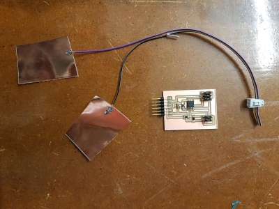
I had far fewer components to solder than last week, so it went by faster. After soldering the board, I also found copper sheets and made my electrodes by soldering on wires to the copper sheets. This was easy as I had a large surface area to work with.
Programming
The next and ideally final step was to program. Following the same steps to program as before, I made the hex files from c file without much problems and attempted to program the usbtiny. Here is where I realized that something was wrong with my board and troubleshooting began.
Troubleshooting
Missing routes from MISO and SCK in 2x3 header to Attiny45
After typing in "avrdude -c usbtiny -p t45", I realized that these routes were missing. I thought I would have to redesign and remill the board since I did not have much space to solder on wires. Luckily, Rob had magical push pin programmers. These push pins essentially acted as temporary 2x3 headers as long as you pushed them down correctly on top of the Attiny45. This meant that I could program the Attiny45 without my soldered 2x3 header, which was great because after programming, I no longer needed the connections to the 2x3 header. Using the push pin, I managed to program the board. I then excitedly ran the python program only to get a signal of 1.

Missing route from Rx in FTDI to Attiny45
I realized that since I was missing all the routes from Attiny45 to header, it was likely that I was missing some other route. I checked and alas, I was missing the route to Rx in FTDI. Luckily, the way my board was designed, I could manually wire to the Rx pin in FTDI. I knew that I did not need the 2x3 header anymore, so I manually disconnected the VCC route to 2x3 header, since this was the only route running directly in front of the relevant Attiny45 pin. The next step was to wire. I was going to use one of the ribboncable wires, but Rob showed me a less-flexible, solid wire that would be easier to solder. Below is the picture of my newly wired circuitboard.

Since the board was already programmed, I reconnected my circuitboard and ran the python program. And voila!
As always, thank you Rob Hart for your help!